A developer's guide for designing the EV charging using the right tool
Introduction
Development boards offer rapid prototyping, reduced development costs, flexibility, and faster time to market for charging concepts. They accelerate prototyping cycles, allows to quickly iterate through designs and test various charging concepts without the need for custom hardware design. This reduces overall development costs and allows for modular designs and customization options. These boards eliminate the need for custom hardware design, allowing for experimentation with different technologies. This cost-effective approach facilitates a more agile development process, allowing engineers to explore creative solutions and address challenges in a resource-efficient manner. Overall, development boards offer a cost-effective and flexible approach to charging development.
EV charging development platform
Electric Vehicle Service Equipment (EVSE) facilitates power delivery to electric vehicles safely from the grid. This is a comprehensive solution for creating efficient and reliable electric vehicle charging stations. It integrates curated hardware and software, streamlining the development process that allows engineers to design smart, connected EV charging stations with Human-Machine Interface (HMI). The platform should be versatile, catering to various charging levels and configurations, tailored to specific needs.
The modular design features make it an ideal choice for accelerating the development and deployment of EV charging infrastructure. It must incorporate communication, safety, and security while providing an easy upgrade path for grid integration. The software includes low-level drivers and the operating system for charging sessions, with production-ready system-on-modules (SOMs) and graphics binaries available to reduce development time-to-market.
The Open Charge Point Protocol (OCPP) is a standard communication protocol for charging stations and their networks (Charge Point Operator - CPO), requiring multiple connectivity options like ethernet, cellular, Wi-Fi, or Sub-1 GHz signals. It supports secure communication and OTA updates, aiming to provide a secure and standardized way for EVs and charging stations to communicate during the charging process.
The components of EV charger
An EVSE control system consists of an auxiliary power stage, an off-board AC/DC high-power stage (only in DC charging stations), energy metering unit, AC and DC residual current detector, an isolation monitor unit, relays and contactors with drive, two-way communication over single wire, and service and user interfaces.
AC-DC converters are used to convert AC power from the grid into DC power. Inverters are used to convert DC power into AC power. Power factor correction (PFC) devices are used to improve the efficiency of AC-DC converters (Figure-1). EV charging stations may also include other power electronics components, such as Isolation transformer which separates the EV battery from the grid, which helps to protect the EV from electrical hazards. Cooling system cools the power electronics components to prevent them from overheating. Control board monitors and controls the operation of the power electronics components.
DC charging station trends support high power and voltage with lower losses. Microcontrollers and power management ICs aim to integrate safety, security, firmware updates, peripheral functions, and reduce the bill of materials (BoM). Gate driver ICs are essential for high voltage support and technology for switching power semiconductors with lower power loss semiconductors.

Figure 1: Main components of EV DC charger
An AC−DC boost converter with power factor correction (PFC) at the front end, followed by a DC−DC stage that provides isolation between the grid and the load (battery of the EV) and regulates the voltage and current at the output. The system may also be bidirectional (particularly at lower power), and thus the topology and design should account for it.
The system includes various components such as an NFC reader, screen, control panel, BLE, PLC, main CPU, ISO15118 stack, OCPP stack, WiFi/LTE, signal conditioning, voltage, current, and temperature sensors for a seamless user experience, ensuring secure authentication, real-time data display, and efficient power management. MOSFET-based designs enable synchronous rectification, higher switching frequencies, and smaller passive components.
Developing custom EV chargers offer unique features and functionalities, such as advanced user interfaces, smart charging algorithms, and integration with renewable energy sources. They can be designed to meet specific requirements, such as charging speed, power capacity, connector types, and user interface. Advanced data collection capabilities are required for in-depth analysis of charging patterns and energy consumption, which can optimize charging operations and make informed decisions. Higher power DC chargers are typically built modularly, stacking power blocks of 15 to 75 kW (and above) in a single cabinet. In general, output voltages of DC chargers range from 150 V to above 1000 V, covering both the 400 V and 800 V standard EV battery levels, and may be optimized for the higher or lower voltage end.
Development platform offerings
Development boards are crucial in designing and testing new electric vehicle charging technologies, ensuring accessibility and efficiency in charging solutions. We will walk through the development board which are used for EV charging system with different power rating output for AC-DC, DC-DC converter.
a. NXP solutionThe EasyEVSE EV charging station development platform offers hardware configuration instructions and example software for establishing secure connections between EVSE and cloud-based applications. This modular platform can be used to build differentiated EVSE systems that support device-to-cloud and cloud-to-device communications, accurate energy billing, and one-tap NFC authentication. It supports cloud services like Microsoft Azure IoT Central service, EdgeLock™ SE050 secure element, Kinetis M metrology MCU for accurate energy billing, and CLRC663 high-performance NFC front-end for one-tap authentication
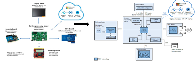
Figure 2: EasyEVSE reference design block diagram
The EasyEVSE (Figure 2) consists of the Host controller (i.MX RT106x cross-over MCU), Meter (KM3x metering MCU), Security (SE050 secure element), NFC (CLRC663 NFC frontend), IoT connectivity (Microsoft Azure IoT Central), GUI- Graphical User Interface. You can find all these products here
The controller block manages communication with the meter, NFC, security, and IoT blocks, providing a GUI interface for monitoring and managing the EasyEVSE. The NFC block reads the UID of NFC devices, while the security block securely stores EasyEVSE credentials for the Azure IoT cloud. The IoT and connectivity block, Azure IoT central application, receives, stores, and displays telemetry from the EasyEVSE into a dashboard. The telemetry is periodically sent to the EasyEVSE dashboard several times per minute.
The dashboard allows real-time modification of EasyEVSE properties, simulating a real application where energy delivered, and tariff cost changes based on grid demand. It also allows sending commands to the EasyEVSE.
b. Onsemi solutionSEC-25KW-SIC-PIM-GEVK - 25 kW SiC-based DC fast charger (DCFC)
SEC-25KW-SIC-PIM-GEVK is a reference design kit for 25kW fast DC EV charger based on SiC power integrated module. This full SiC solution consists of PFC and DC-DC stages featuring multiple 1200V, 10 mohm half-bridge SiC modules NXH010P120MNF1, the ultralow RDS(on) and minimized parasitic inductance can significantly reduce conduction loss and switching loss.
The system shall cover a wide output voltage range, able to charge EVs with both 400 V and 800 V batteries, optimized for the higher voltage level. The input voltage is rated for EU 400 Vac and US 480 Vac three−phase grids. The power stage shall deliver 25 kW over the 500 V to 1000 V voltage range. Below 500 V, the output current will be limited to 50 A, derating the power in alignment with profiles of DC charging standards such as CCS or CHAdeMO (Figure 3).
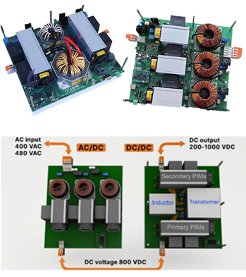
Figure 3: Evaluation kit - SEC-25KW-SIC-PIM-GEVK
Regarding communication ports, the board will provision isolated CAN, USB, and UART infrastructure for external interfaces (between power blocks, charger system controller, vehicle, service, and maintenance)
The system can deliver maximum 25kW over 200V-1000V output voltage with 96% all-time efficiency to charge 400V or 800V EV batteries.
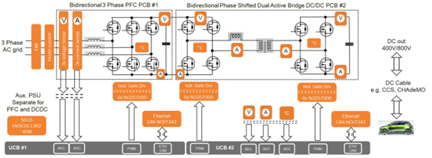
Figure 4: 25 kW EV DC charger power stage high−level block diagram
As shown in the figure 4, it utilizes two universal controller board (UCB) designed with Zynq®-7000 SoC FPGA and ARM®-based processor
SEC-25KW-SIC-PIM-GEVK also highlights the galvanic-isolated high-current driver NCD57000, auxiliary power solution SECO-HVDCDC1362-40W-GEVB to power stable voltage rails to low-voltage components, integrated protections like inrush control, over voltage protection and multiple interfaces for communication.
c. Infineon solution- REF-DAB11KIZSICSYSThe REF-DAB11KIZSICSYS board is a DC-DC stage with a wide range output using two inductors and two capacitors (CLLC) resonant network with bi-directional capability. This converter can operate under high power conversion efficiency, as the symmetric CLLC resonant network has zero-voltage switching capability for primary power switches and synchronous-rectification commutation capability for secondary side output rectifiers. The converter could change the power flow direction, and its maximum power conversion efficiency was around 97.2% during the operation without synchronous rectification.
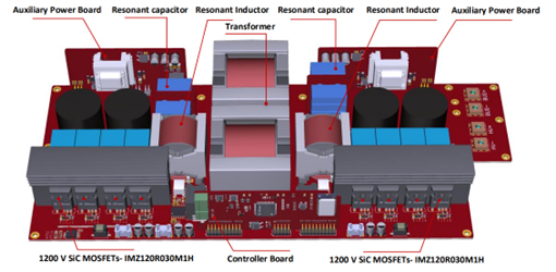
Figure 5: REF-DAB11KIZSICSYS board
The 11 kW SiC bi-directional DC/DC converter board is designed for EV charging and energy storage systems (ESS) applications. It features a CLLC topology and is suitable for chargers from 30 kW to 150 kW. The board uses 1200 V CoolSiC™ MOSFETs in a TO247-4 package and EiceDRIVER™ 1ED compact gate driver ICs, enhancing efficiency, space and weight savings, part count reduction, and system reliability.
Conclusion
The discussion highlighted the importance of prototyping, modular solutions, and development boards for custom-built EV charging stations. These tools allow engineers to quickly construct and test innovative charging concepts without hardware design, reducing the time needed to introduce new products to the market. This highlights the efficiency and effectiveness of these development tools in EV charging station creation.
Below is list of few EV charging development boards:
| Supplier | Part no | Description | Order code |
|---|---|---|---|
| PHOENIX CONTACT | EV-SET-T2AC-BAS-RCM1-20AC5MES | TWIN CHARGING TECHNOLOGY SET STARTER KIT | 3294737 |
| PHOENIX CONTACT | EV-SET-T2AC-ADV-RCM2-32AC5MES | TWIN CHARGING TECHNOLOGY SET STARTER KIT | 3294735 |
| PHOENIX CONTACT | EV-SET-T2AC-ADV-RCM2-32ASE12 | TWIN CHARGING TECHNOLOGY SET STARTER KIT | 3294736 |
| PHOENIX CONTACT | EV-SET-T2AC-BAS-RCM1-20ASE12 | TWIN CHARGING TECHNOLOGY SET STARTER KIT | 3294738 |
| TRINAMIC / ANALOG DEVICES | TMC4671-LEV-REF | Reference Design Board, TMC4671, Light Electric Vehicles | 3765363 |
| Onsemi | SECO-GDBB-GEVB | Gate drivers plug-and-play ecosystem | 3528526 |
| Onsemi | SECO-LVDCDC3064-IGBT-GEVB | 6 - 18 Vdc Input Isolated IGBT Gate Driver Supply +15 V / -7.5 V / 7.5 V with Automotive Qualified NCV3064 Controller | 3766234 |
| Onsemi | SECO-LVDCDC3064-SIC-GEVB | 6-18 Vdc Input Isolated SiC Gate Driver Supply +20V/-5V/5V with automotive qualified NCV3064 controller evaluation board | 3766235 |
| Infineon | EVAL-1ED3321MC12N | Evaluation board for EiceDRIVER™ F3 Enhanced with short-circuit protection | 3931196 |
| Infineon | REF-DAB11KIZSICSYS | 11 kW SiC bi-directional DC/DC converter board for EV Charging and ESS applications | 3766011 |
| Infineon | EVAL-FFXMR12KM1DR | Evaluation board for 1200 V CoolSiC™ MOSFET 62 mm half-bridge modules | 3865650 |
| Infineon | EVAL3K3WLLCHBCFD7TOBO1 | Evaluation Board, Power Management, IPW60R018CFD7, Digital LLC Resonant Half-Bridge DC-DC Converter | 3514696 |
| Infineon | 3865650EVAL3K3WBIDIPSFBTOBO1 | Evaluation Board, Power Management, IPL60R075CFD7, Bidirectional DC-DC Converter | 3514695 |
| Infineon | EVAL2KWZVSFBCFD7TOBO1 | Evaluation Board, Full Bridge Solution, SMPS, ZVS PSFB, Industrial/Server Applications, 2kW | 2981496 |
| ST Microelectronics | STEVAL-DPSTPFC1 | Evaluation Board, TN3050H-12WY & SCTW35N65G2V, Totem Pole PFC with Inrush Current Limiter | 3642958 |
Below are the development boards used in EV charging
| Embedded development kits - ARM |
| IoT solutions kits |
| DSPIC Dev boards |
| Embedded SBC boards |
| Power management development kits - AC / DC |
| RF modules |
| Communications & networking modules |
| Embedded software |
Stay informed
Keep up to date on the latest information and exclusive offers!
Subscribe now
Thanks for subscribing
Well done! You are now part of an elite group who receive the latest info on products, technologies and applications straight to your inbox.

Fuelling the future
A journey towards sustainable mobility!

Electric Vehicle (EV) Charging Solutions
A comprehensive guide
Related Article
- Charging protocols and safety standards for EV Charging Infrastructures
- The Future of EV Infrastructure: Navigating trends, opportunities, and benefits
- A Developer's Guide for designing the EV Charging using the right tool
- Revolutionizing Electric Vehicles - Innovations in Motor Control Systems
- How to implement Smart Metering in EV charging
- How to design an efficient power conversion circuit for EV Chargers
- Transforming Mobility: The Architecture and Solutions of V2X Communication in Electric Vehicles
- The effects of electric vehicle charging stations to the power grid
- Cyber security of public charging stations
- Powering Up with Safety and Ease: The Art of EV Charger Design
- EV Charging Standards: Ensuring Compatibility and Safety in the Charging Process
- EV charging and renewable energy for sustainable transportation
- EV Charging and Battery Management System
- Wireless Power Transfer: A Convenient and Efficient Solution for EV Charging
- Design Considerations for High-Efficiency EV Chargers
- The benefits and challenges of electric vehicles
- Communication network for electric vehicle charging
- How to boost Level-3 EV charging with the right connectivity
- How SPI isolated communication helps BMS in EVs